
KF2HP Clock Project
Daniel H. Pressler, KF2HP
GPS UTC/Local clock project
I like to know what the local and UTC time is when I’m at my HAM equipment. I had two clocks hanging on the wall. One 24 hour clock for UTC and another 12 hour clock for local time. The 24 hour clock was “Atomic” which means it was suppose to synchronize once every 12 hours from WWV. In our house my shack was relegated to the lower level of our house. The “Atomic” clock never had sufficient RF signal to synchronize and of course there is no external antenna connection. It seemed like I was always taking the clocks off the wall, correcting the time and putting them back up on the wall. One day I was playing with an app on my smart phone that displayed the number of visible GPS satellites and I noticed that at least 3 were available most of the time. Armed with this information I set out to build a clock that displayed UTC and local time and was kept accurate using the GPS satellite constellation.
To be successful with the project you need to be able to see satellites from where you expect to put the clock. There are many apps available for various devices that will give you that information. I have even seen some navigational devices that have a screen that will show you the satellite coverage.
The next thing I did was dig through the junk box for an appropriate enclosure. I found a nice plastic instrumentation box that had plenty of room for everything I needed. Actually I had a little more room than necessary in terms of front panel real estate so I decided to also include a 10 minute countdown timer to remind me to ID when on the air. Remember it’s important to use a plastic case as the GPS shield has the antenna built in. I don’t think it would work as well if it was put in a metal box.
I continued scrounging through the junk box and came up with an Arduino Uno and an LCD display. The LCD display I had was parallel input so it needed a minimum of 4 lines between it and the Arduino plus the common power and ground leads. If I was going to use 3 of these I would be using more IO capacity on the Arduino than I could afford. So I started looking at options. Using serial interface to the LCD displays seemed like the logical answer as I only needed two pins on the Arduino to drive all three LCD displays. I looked at the displays that were already setup for I2C interface but you had to change their address with software commands. I discovered some piggy back devices that would go on the back of the standard parallel LCDs and you can change the addressing by shorting solder tabs on the back. So that’s the method I chose.
I ordered three 16 character by 2 line LCDs with parallel to I2C piggy back boards. These can be purchased from a variety of places. Some even have the LCDs and piggy back boards combined. I would strongly suggest you invest in a proto shield with through headers to put between your Arduino and GPS shield. This gives you a place to mount components and gives you easy solder access to the various pins on the Arduino. I ordered a GPS shield from Dexter Industries as it was around $20 and had all the features I needed. The particular model I used has been discontinued and replaced by a better model however it is now priced at around $30.
I found a 12 volt switching power supply in the junk box so I decided to use it as I have an aversion against walworts. Of course you can use whatever you like. The Arduino Uno has a 5 volt regulator onboard so it needs something between 7 and 12 volts for proper operations. I measured the current on the input to the Arduino and it was about 800ma with the GPS shield and all three LCDs plugged in. I also used the 12 volts to power another board that I put a relay with a buzzer on to alarm when the ID timer counted down to zero.
I found a nice SPDT switch for the ID timer. It was positive in one direction and spring loaded in the other. This made it nice as I could put it down to turn off the timer. Put it in the middle position to run the timer then use the spring loaded position to reset the timer. I also included a couple LEDs to show the presence of power and another to indicate I was seeing at least three satellites.
The two biggest challenges with this project were finding the correct libraries for things and to get the addressing to work on the I2C devices. So I’ll try to save you some trouble.
You can download the libraries and software I used here: http://www.megexcel.com/UTC_Local_Clock/UTC_Local_Clock.zip
The first think in dealing with all this good stuff is downloading the current version of the Arduino IDE. This is the development environment for the Arduino programming and directions in using it is beyond the scope of this article. After getting the IDE to work, unzip the files and copy the library files to the appropriate place in the Arduino directory structure. I have included two sketches (that’s what the Arduino IDE calls the code), one sketch is called I2cScanner and the other is the sketch for the clock.
I was having great difficulty getting the I2C to work between the Arduino and the LCDs until I ran across an article on one of the Arduino user groups. Essentially it said to never trust what the vendor tells you about addressing as the addressing scheme is somewhat convoluted. They suggested using the I2cScanner, hooking up your I2C device and the I2cScanner will scan all the addresses on the I2C buss and tell you which one it gets a response from. I would suggest you use this process to verify that you know what the addresses really are. I’m sure there are ways to calculate it but I think this is a much easier and sure way.
This project is very flexible and only limited by your imagination and what you want to accomplish.
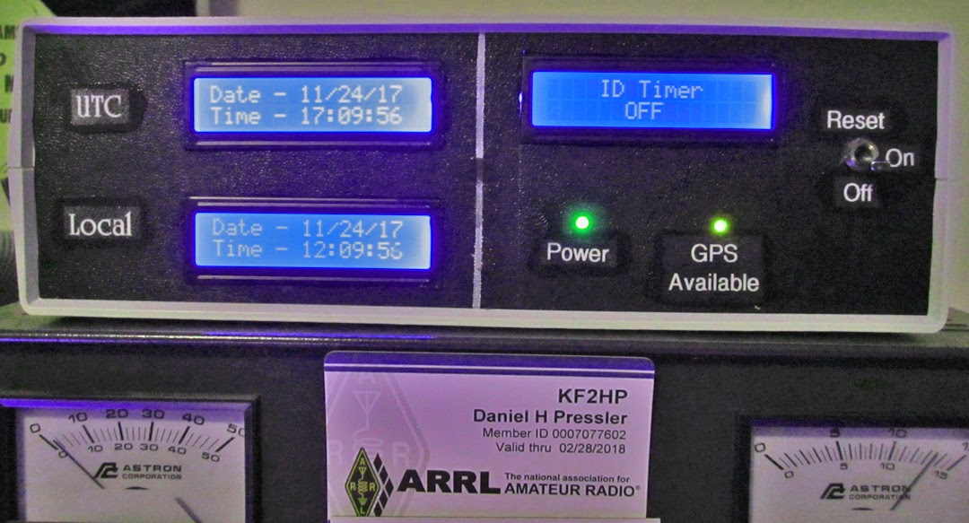
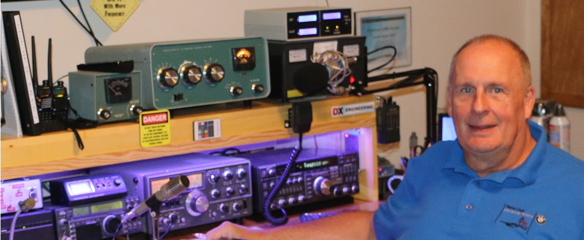
Figure 1 shows my finished unit sitting on top of my power supply.
Figure 2 is a schematic of the outboard components.
I also have an LED fed directly off the power supply to indicate the presence of output from the power supply. I soldered the current limiting resistors in series with the leads of the LEDs and put heat shrink over them as an easy place to put them.
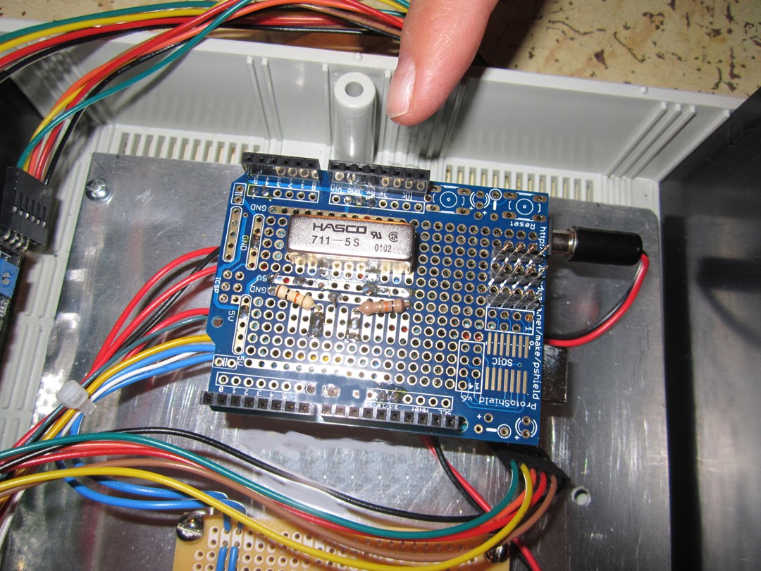
Figure 3 shows the layout of the proto shield I put between the Arduino and the GPS shield. You can see the reed relay I used to activate the alarm when the countdown timer got to zero and the two 10K pull down resistors on the lines from the front panel toggle switch.
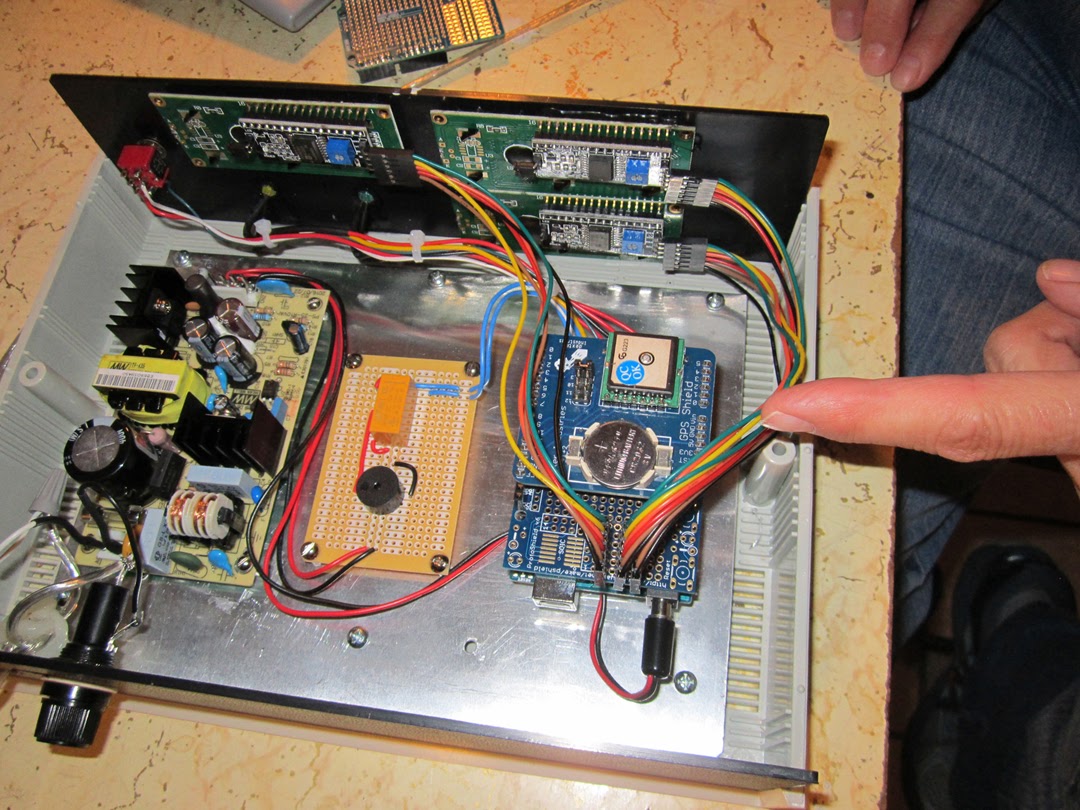
Figure 4 shows the three bundles of wires coming off the multiple on the proto shield to each of the three I2C piggy back boards on the LCDs.
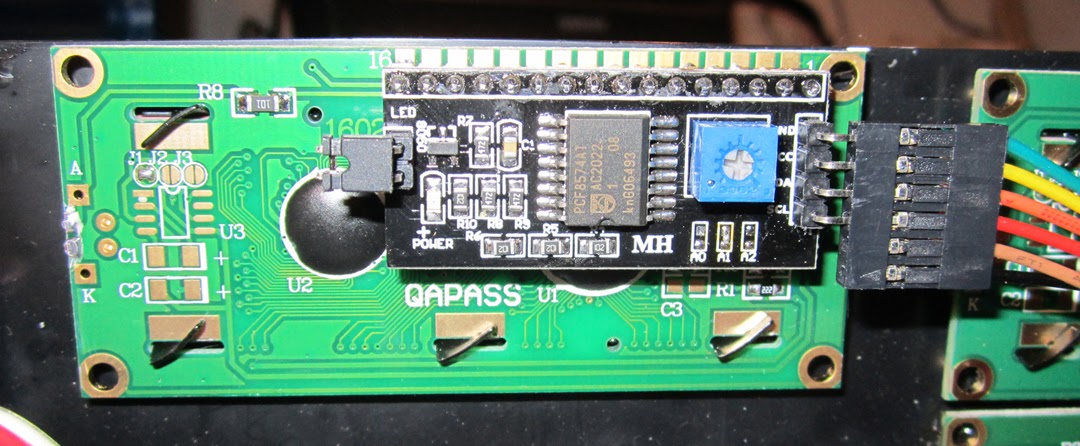
Figure 5 shows one of the piggy back I2C boards. You can see the three sets of solder pads under the blue cased potentiometer. The potentiometer is used to set the intensity of the LCD display.
The sketch to accomplish all this is annotated so you can get a grasp of how it works. There are variables in the sketch that are clearly defined and must be changed for time zones other than the Eastern Time zone. Again, this article is not intended as a guide in programming the Arduino. I don’t consider myself a programmer and I’m sure there are better ways to accomplish things. But this will give you a starting point.
I must give credit to Craig Clark, N5XNQ who wrote an excellent algorithm for converting the UTC time to local time in January of 2014 and used ideas by Jeon Jinsook at jeonlab.wordpress.com in September 2013. I must also thank Mike Craycroft, KE4KOP for his suggestions and Gary White, WA0ASA for his constant encouragement and suggestions.
Enjoy and have fun.
Dan, KF2HP